
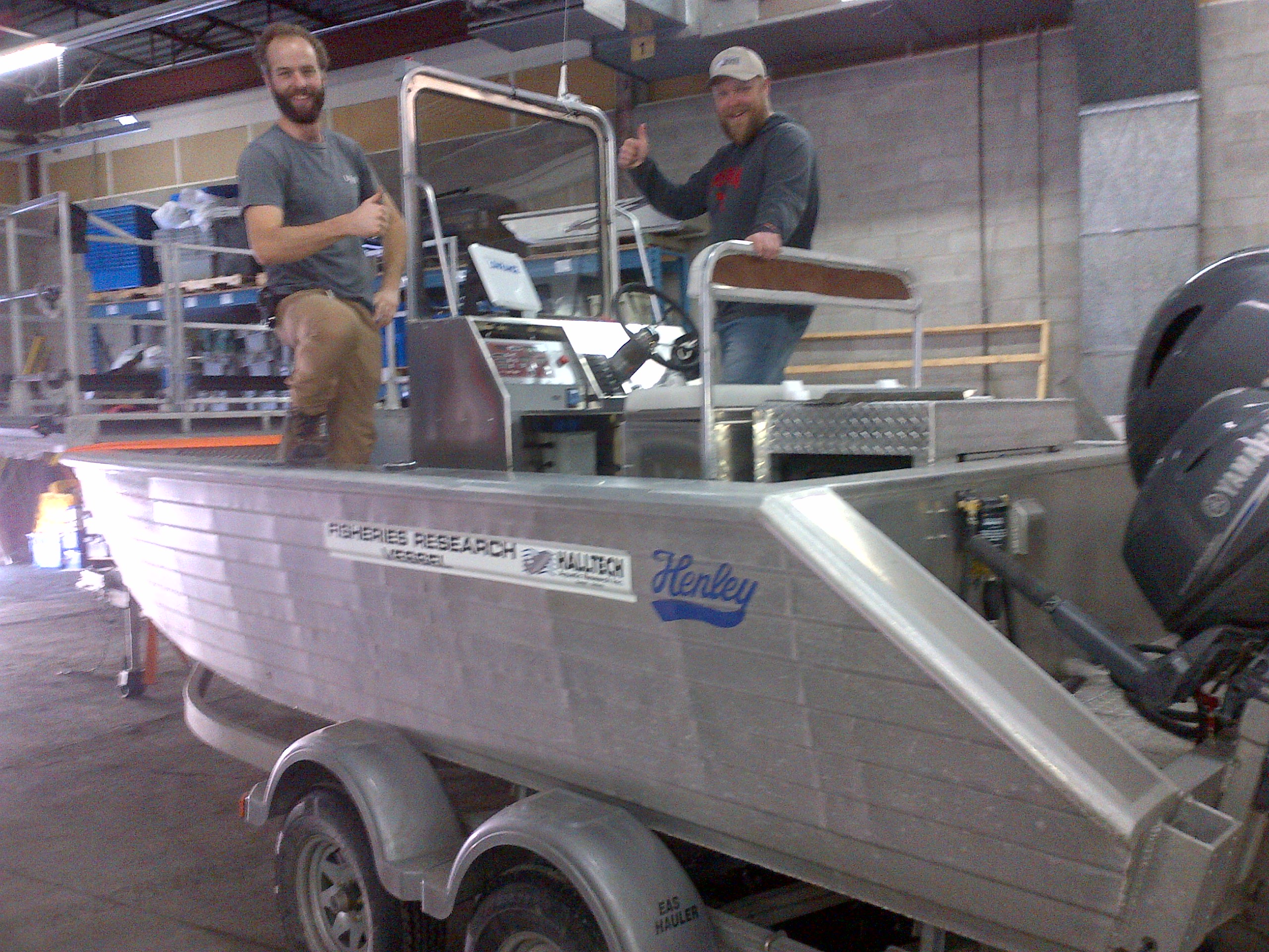

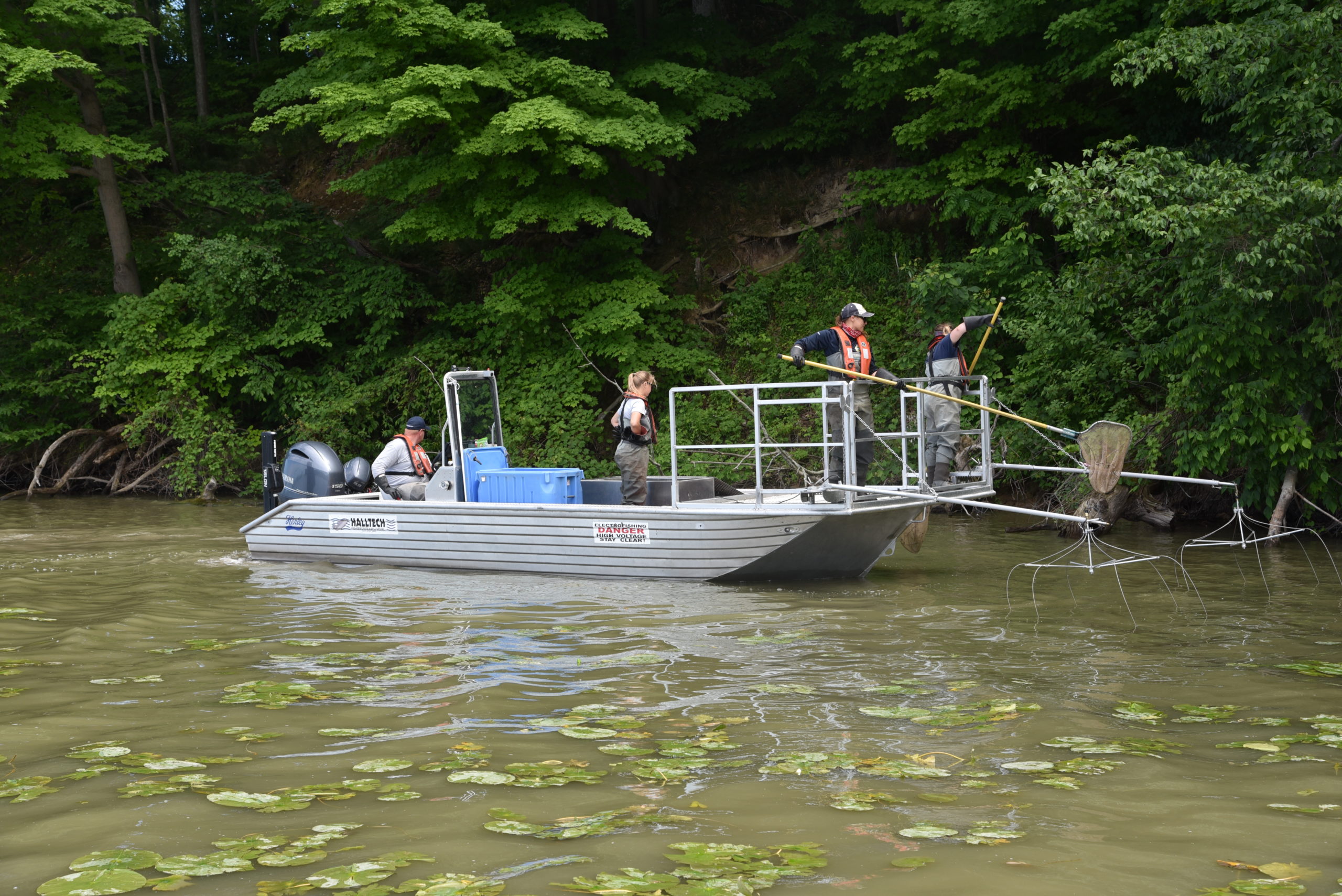
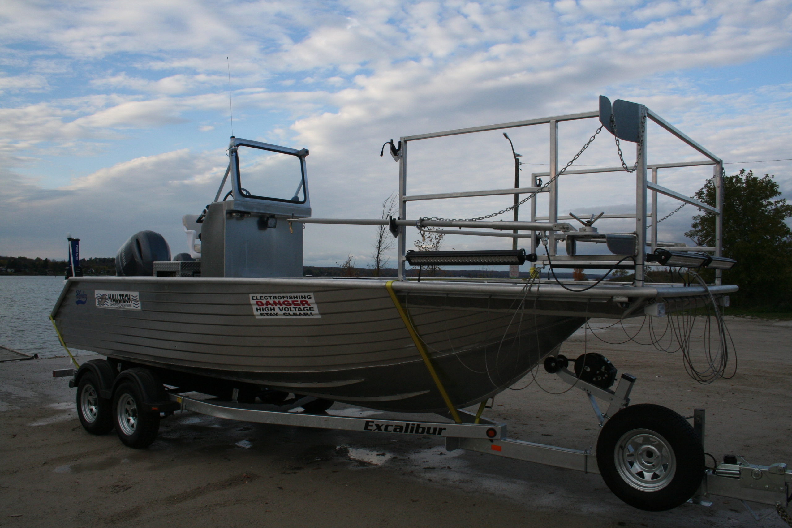
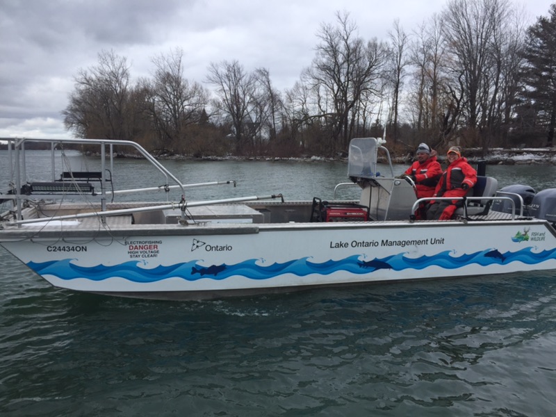
Halltech Electrofishing Boats
Halltech is has been building turn-key Electrofishing Boats for over ten years. Our Henley and Stanley hulls are considered the toughest in the industry and ready for the rough water experienced on the Great Lakes. We also offer an extreme shallow draft flat bottom design and pontoon rafts for very shallow inland rivers.
We customize every boat to the unique requirements of each customer and they are meticulously build for many years of service and any conditions.
We are the proud Canadian Distributor and Technical Resource Center for the MLES Infinity and HC-80 Pulse Controller which provides the most perfect combination of power and portability in the industry!
Description
HALLTECH AQUATIC RESEARCH INC.
INFINITY CONTROL BOX – OPERATION GUIDE
Halltech Aquatic Research Inc.
129 Watson Rd S
Guelph, Ontario- N1L 1E4
519-766-4568
sales@htex.com
Read more...
1
TABLE OF CONTENTS
Electrofishing Equipment Safety ………………………………………………………………………………………..2
Introduction…………………………………………………………………………………………………………………….3
Getting Familiar With The MLES Infinity Control Box ………………………………………………………..4
Operation The MLES Infinity Control Box ………………………………………………………………………..10
Maintenance And Troubleshooting……………………………………………………………………………………22
Warranty Information. …………………………………………………………………………………………………….23
Appendix A……………………………………………………………………………………………………………………24
Contact Halltech ……………………………………………………………………………………………………………….27
ELECTROFISHING EQUIPMENT SAFETY
Safety Considerations For Electrofishing
Boat mounted electrofishing systems use currents and voltages in either an AC or DC waveform that can be injurious or lethal to humans. When using the MLES Infinity Control Box, the boat hull is wired as the cathode. The insulated booms, extending approximately 7ft in front of the boat, support the metal dropper arrays (anodes). High voltage exists between the droppers (anode) and the boat hull (cathode) as well as the water surrounding the boat.
All personnel involved with electrofishing should be trained in electrofishing safety protocol. It is highly recommended that users of this equipment attend a formal electrofishing training course.
Be absolutely certain that the generator frame is electrically bonded to the hull of the boat with a #8 AWG wire or heavier.
Ensure that a properly designed safety cage is positioned on the bow of the boat to protect the dippers from entering the water. Never bypass the safety switch, pad or mat used by the dippers.
NEVER transport or store the Infinity Control Box in an electrofishing boat while trailering. ALWAYS remove the control box from the electrofishing boat prior to trailering. Secure the Infinity Control Box inside the tow vehicle for safe transport.
Equipment Inspection
All components of an electrofishing system (control box, booms, anodes, wire insulation, junction boxes, bonding, safety switches, plugs, electrical connections, etc.) should be inspected prior to each use. Moisture, vibration, and general use can cause corrosion and loosen connections. Cuts and nicks in wiring and other damage to parts with use may occur as well.
Always ensure that every aspect of the electrofishing system is well maintained and in top- working order without any defects. This ensures safety and an efficient electrofishing system.
Any repairs should only be made when the system is off, powered down, and not in use. Never attempt to diagnose problems, make repairs, or perform maintenance while the system is powered on or in use. The capacitors inside the system will maintain a lethal charge for several minutes after power is removed. Untrained personnel should not make repairs without written approval from the manufacturer or a qualified electrical engineer.
INTRODUCTION
The MLES Infinity Control Box has been engineered to meet the boat-mounted electrofishing needs of most freshwater environments. It is designed to be used with any commercially available 60 Hz, 240 volt AC generator that has an isolated case neutral. The size of the generator can range from 3,000 to 9,000 watts depending on the power requirements needed by the end user for effective sampling. The Infinity Control Box should never be connected directly to 240 VAC available from your facility’s breaker panel. Generally, the impedance is too low and the resulting current surges will damage the electrofishing unit.
The Infinity Control Box uses the latest electronic hardware and software and features Intelli- Shock© technology to allow for the simplest and safest operation. This modern technology includes many safeguards to ensure longevity of the box, advanced overload protection, and automatic voltage range shifting capabilities. The Infinity Control Box is also comprised of many water resistant components and splash resistant features to maintain operation in harsh conditions.
Specifications
Input Voltage: 240 volt AC, 60 Hz; from generator with isolated neutral Output Power AC: 0-7,200 watts (may be pulsed)
Output Power DC: 0-12,000+ watts (pulsed); 5,500 watts continuous Output Voltage AC: 0-240 V, 30A RMS (root mean squared)
Output Voltage DC: 0-1200 V, 40A peak (duty cycle dependent) Pulse Rate (AC Frequency): Incrementally adjusted with specific duty cycle
Pulse Rate (DC Frequency): 1-300 pulses per second DC (adjustable in 1pps increments) Duty Cycle AC: Incrementally adjusted with specific pulse rate
Duty Cycle DC: 1-100% (adjustable in 1% increments)
Dimensions: 16” L x 12” W (deep) x 11” H (40.6 x 30.4 x 27.9 cm)
Box Weight: 29lbs (12.7 kg)
Control box housing: Aluminum
Storage Temperature: 0°F to 154°F (-17.8°C to 67.8°C)
GETTING FAMILIAR WITH THE MLES INFINITY CONTROL BOX
Front Panel Features
Emergency Stop Button: This large red prominently displayed button is easily located in the front just right of center for quick and easy access. It is illuminated when the Box is reset and in use. If the button is in the depressed (Stop) position, the button must be turned one-quarter (1/4) turn clockwise (to the right) and reset before electrofishing can be resumed. This button lights up when the foot switch is active and the system is ready to energize the output.
Water resistant electric/hydraulic main power breaker: The main power breaker is positioned on the front of the Box and housed in a water-resistant jacket to ensure continued reliable use while in operation.
Control Panel: The control panel functions as the user interface, displaying system settings and allowing the user to make necessary adjustments to system settings (i.e., Power , Amps, Voltage, Pulse Rate and Duty Cycle). All displays are illuminated with a red background for easy viewing during low light or nighttime electrofishing with the exception of the system information display, which uses a white back light.
Control Panel Function Descriptions
A – System Information digitally displays data for monitoring and setting system parameters:
Resettable fishing time (hh:mm:ss)
Generator input to control box (frequency and volts)
Overall control box hour usage meter (hh:mm:ss)
Dimmer control (levels 0 – 3) for backlighting.
Set Voltage Range (Low Range Ceiling, Mid- Range Ceiling, Automatic)
Display and power board revisions.
Pulses and Duty Cycle pressing (F) or (G) and adjusting (I)
Save and Recall for presets (1-8) pressing (H) and adjusting (I)
Section also displays (flashes) operational notifications such as voltage range shifts, overloading, output shorted, generator and foot switch status.
B – Timer Reset. Press button to reset fishing time (not functional during data recall). C – Displays peak output amperage while the Box is operating.
D – Displays peak output power (watts) while the Box is operating.
E – Displays peak output voltage while the Box is operating; adjusted by (M).
F – Pulses button used to select for pulse rate/frequency (Hz); adjusted by (I); monitored in (A).
G –Duty Cycle % button used to select duty cycle (%); adjusted by (I); monitored in (A).
H – Generator Freq./System Info button used to toggle through all items in (A). Press for data recall* when the Box is powered down.
I – The up/down buttons increase/decrease by one unit or hold down for fast increment. Press to save and recall preset electrofishing settings.
J – The DC button is used to select for DC electrofishing.
K – The Reset button must be pressed to begin electrofishing. Press the Reset button following turning the main breaker button to ON and twisting the Emergency Stop button one-quarter (¼) turn clockwise to reset.
L – The AC button is used to select for AC electrofishing and may be pulsed.
M – The up/down buttons change voltage by one volt or hold down for fast increment.
*Note: The Infinity Box offers a “Data Recall” feature that displays the settings in use when the Box was last powered down. The settings (pulses, duty cycle, volts, fishing time) may be recalled by pressing button (H). In addition, foot switch continuity may be tested when data recall is selected. Thirty seconds after the last button is pressed, the display will turn off. The display is powered by a nickel metal hydride rechargeable battery. The charge on the battery lasts 6 months without powering up the control box.
Rear Panel Features
External Fuse Housings: Three 25 amp fuses mounted externally in watertight housings. One spare fuse included on top right at rear of box.
Uniquely Keyed Plug Receptacles: The Infinity Control box requires three main plugs for proper connection and function. The main input plug from the generator (240 VAC Generator Only) is a five socket plug. The foot switch plug has three pins. Power output to the booms is a four pin plug (Figure 4).
All plugs are UV resistant, rated for 32A, contain O-rings and gaskets, and have positive locking keyways that only terminate into the correct receptacle. These receptacles provide a watertight seal for the primary electrical connections. Always use two hands to connect and disconnect a plug. Hold the black portion of the plug with one hand and turn the blue coupler with the other hand.
THREE 25 AMP WATER TIGHT FUSES
SPARE FUSE
OUTPUT TO BOOMS
FOOT SWITCH
INPUT FROM GENERATOR
Note that each plug is uniquely keyed to eliminate the chance of improper connection. Output power plug from Box to booms: red wire to port anode (+), black wire to starboard anode (+); green and white wire are cathode (-), bond together and attached to boat hull.
Advanced Safety Features
Internal electronic circuitry protection: This feature prevents the control box from becoming damaged due to an overload. Should a potential overload situation be detected by the control box circuitry (such as a rapid increase in water conductivity that causes a current surge), the output voltage will automatically be reduced until the current is in a safe operating range. If the water conductivity goes back down, the voltage will automatically rise back to the set value. If the potential overload condition persists, “overload” is flashed and displayed in the system information/status bar, and the emergency stop button will flash to indicate the supply has reduced the fishing voltage. It will continue to flash after the overload has been removed. Press the Volts down button to reset the error. If the Box is still in overload, the error will be turned back on immediately.
Remote safety switch for use by dippers: The foot switch input allows easy, convenient control of the MLES’s output.
High voltage soft start: This feature ensures generator and system safety. The output is quickly ramped from zero to the desired output voltage. If an over current condition occurs, the voltage increase is stopped and an overload condition is triggered. This prevents damage if the fishing conditions have drastically changed.
DC /AC selection on the fly: The user may select a different waveform while the MLES is in use without powering down. When a change in waveform is selected the output power will be automatically – but temporarily – turned off. The power supply will automatically be reconfigured and the voltage will be turned back on to the new waveform (this may take a moment if the supply is waiting for the capacitors to discharge).
Automatic voltage range shifts for three ranges of voltage: The MLES Infinity Control Box contains three banks of capacitors that are charged and discharged to produce pulsed output waveforms. These capacitor banks are configured to operate at three distinct voltage ranges [Low (0-300V), Mid (300-600V) and High (600-1,200V)]. When the user chooses to operate in one of the two upper two ranges, the Box will automatically shift from the lower range into the next higher range without the user having to power-down the box. This “range shift” will cause a momentary delay as the Box shifts to the next range of voltage, during which time a message “Voltage Range Shift” will be displayed in the system information display. Similarly, when operating the Box near the transition between two voltage ranges (i.e., the shift point), the box may attempt to shift into the next higher range. This too will be accompanied by a momentary delay and a Voltage Range Shift message. For additional information regarding voltage ranges and range shifting, please refer to the Advanced Operation – Range Shifting, Range Ceilings… section later in this manual.
Dead short protection: Protects internal circuitry of the Box if anode makes contact with the cathode. Clear anode from cathode and/or check for improper wiring of the electrofishing system. For additional information of dead short protection, please refer to the Indicators and Messages from Control Box While Electrofishing section later in this manual.
OPERATING THE MLES INFINITY CONTROL BOX
Basic Operation Procedures
MLES Infinity Control Box must be positioned in a secure place for operation.
Remove dust caps. All cords (input, switch, and output) must be plugged into the rear of the MLES Infinity Control Box and firmly tightened (Figure 3).
The generator must be started and increased to full RPM’s to reach an output of 60Hz and 240 volts. The main breaker of the Box must be placed in the up (ON) position.
The LCD display windows on the front panel will become illuminated upon start up.
When the Box is turned on, “Fishing Time” will appear in display (A). Generator output may be monitored in display (A). Use the select button (H) if not already shown in the display to monitor generator frequency output and voltage. Please reference Figure 2 for button locations.
Select the desired waveform output type DC+ (J) or AC~ (L).
Preset desired level of “Pulses” by pressing select button (F) then increase or decrease with select button I.
Preset desired “Duty Cycle %” by pressing the select button (G) then increase or decrease with select button (I).
If desired, preset the voltage by pressing (M) to increase or decrease the volts (voltage shown in display E).
If desired, preselect a voltage range (Low Range Ceiling, Mid Range Ceiling, Automatic). Press (H) to select set voltage range function, then press (I) to select desired range. Refer to Advanced Operation in the following section.
If desired, eight programmable electrofishing settings can be saved and recalled (waveform – AC or DC, duty cycle, pulse rate, and volts). Press (H) to scroll to save and recall shown in (A), then press (I) to save and recall settings. Refer to Advanced Operation in the following section.
Reset fishing time with the “Timer Reset” button (B) when appropriate.
Disengage “Emergency Stop” by turning ¼ turn clockwise. It will “pop” out and click.
Press the Reset button (K) and “Emergency Stop” will illuminate. Dashes will appear in the Power (D) and Amps (C) displays. Volts (E) will display set voltage.
NOTE: The two previous steps may be performed in reverse order with – press Reset then disengage “Emergency Stop.”
Instruct dipper to depress (step on) bow foot switch to complete the circuit and commence electrofishing. NOTE: A click (capacitors engaging) will be heard from the MLES Infinity Control Box when DC is in use.
Power (Watts) will appear in display window (D) and Amps in display window (C).
11
NOTE: If the Emergency Stop Button is not disengaged as instructed above, or the reset button has not been pressed, and a dipper engages the foot switch, zeros will appear in Power (Watts) and Amps display and no output will occur.
Monitor fish response and adjust voltage accordingly to attain desired Amps and Power (Watts) to immobilize fish.
CAUTION: Shorting (contact with) the anode (+) to the cathode (-) while the MLES Infinity Control Box is operating will cause damage to internal circuitry.
Advanced Operation – Range Shifting, Range Ceilings and Current Limitations/Overload
Range Shifting: The Box offers three voltage ranges (Low Range = 0-300V; Mid-Range = 300-600V; High Range = 600-1,200V) to provide efficient electrofishing over a wide range of conductivities (Table 1). The low voltage range will normally be used in relatively high conductivity water, whereas the higher ranges will be most effective in lower conductivity water. The Box allows the user to easily transfer from one voltage range to the other by incrementally increasing or decreasing the voltage selector button. Note: shifting from one range to the next higher range will be accompanied by a momentary loss of output power and a “Voltage Range Shift Please Wait” message. This is due to the Box engaging an additional bank of capacitors to facilitate the higher voltage range. When the additional capacitor bank becomes appropriately charged, normal electrofishing will resume automatically.
Table 1. Relationship between voltage range, maximum amperage and duty cycle (%) when operating the
Infinity Control Box in DC mode.
Maximum amperage allowed within voltage range
Voltage Range (volts) Duty cycle (1-25%) Duty cycle (25-50%) Duty cycle (50-100%)
Low (0-300) 40 amps 40 amps 40 – 20 amps*
Mid (300-600) 40 amps 40 – 20 amps* 20 – 10 amps*
High (600-1,200) 40 – 20 amps* 20 – 10 amps* 10 – 5 amps*
* Maximum amperage decreases exponentially as duty cycle is increased.
Range Ceilings: In certain electrofishing scenarios, the user will find that the voltage required for optimal electrofishing efficiency occurs at or near one of the shift points between two voltage ranges (e.g., 300 or 600 volts). If a change in water conductivity is encountered while the Box is near the shift point, the box may attempt to deliver more voltage to adjust to the change in conductivity. This can trigger a range shift and a momentary loss of output power. This can be prevented by selecting to use the “Low Range Ceiling” or the “Mid Range Ceiling” setting on the Box, thus preventing the Box from automatically shifting into the next higher range.
Current Limitations/Overload: The Box can provide enough output power (12,000 Peak Watts) to effectively electrofish over a wide range of water conductivities. However, in order to deliver such high peak power outputs, the duty cycle (% of the pulse that is energized) must be reduced as the power requirement is increased. Otherwise, the power required would exceed the capabilities of most generators. For example, if the user desired to operate the Box at 600 Volts, 20 Amps, and a 100% Duty Cycle, that would equate to a continuous, average power output of 12,000 Watts; far more than could be produced by even a robust 7 KW generator. Therefore, the Box places a limit on the maximum output current that can be provided, and that limit varies exponentially as a function of the duty cycle of the output pulse selected by the user.
If the user is attempting a shift from one voltage range into the next higher voltage range, but the current is too high for the range shift to occur, the Box will alert the user of a possible overload condition. Similarly, if the user is operating near the maximum current limitation for a given voltage and duty cycle, and the Box senses an increase in water conductivity that causes the amp draw to increase, then the Box will alert the user of an overload condition. If this occurs, the user should reduce the voltage and/or reduce the duty cycle to alleviate the potential of causing an overload condition.
Advanced Operation – Save and recall preset electrofishing settings
Eight programmable electrofishing settings may be saved and/or recalled. Save a setting Select desired waveform (AC or DC), duty cycle, pulse rate, and volts.
Press (H) to scroll through until the display reads “Save 1” in (A). Stop fishing (step off switch) to save settings then press and hold (H) to save.
The display (A) will ask “Sure?” to save. Press (I) up arrow to save the setting to Recall 1. If not sure, press (H) to clear out of save.
Repeat procedure to save additional settings (2 – 8). Save up to eight electrofishing settings. Repeat save procedure to write over any Recall setting.
Recall a saved setting. Press (H) until Recall is shown in (A). To view saved settings in (A), scroll (I) up or down to select desired Recall (1-8). Stop fishing (step off switch) to recall the desired setting. Press and hold (H) to recall the setting.
The display (A) will ask “Sure?” to recall. Press (I) up arrow to use the selected Recall setting.
Indicators and Messages from Control Box While Electrofishing:
If Volts (E) flashes and the systems info display (A) reads “Overload Fishing Voltage Reduced” there is a potential overload and you must step off the foot switch. The MLES Infinity Control Box will automatically reduce the voltage to a safe setting and then return to the set voltage. Use the (M) select button to reduce the voltage to a safe setting.
If more power is needed to effectively sample, continue to increase voltage until the volts display (E) flashes. When the voltage approaches the upper limit of a specific range, the system information display (A) will indicate that a “shift is in progress.” This will momentarily lock out the user as additional capacitors engage to facilitate the voltage range shift. Once the bank of additional capacitors come online, the box will resume normal electrofishing functions. When an incremental adjustment is made with the increase/decrease buttons (Figure 2), the symbol ” ” will appear in the top left corner of the display windows (Power, Amps, Volts). It appears for a change in pulses, duty cycle, dimmer level, and volts. The symbols + for DC and ~ for AC will appear in the Amps and Volts display windows when the respective output is selected (select button J or L).
If Emergency Stop is pressed during electrofishing, the system information display will flash “Foot Switch Check Step Off Switch.” Before electrofishing can resume, the Emergency Stop switch must be disengaged (out position), the dipper must step off the foot switch, the operator must press the Reset button, then the dipper must step back on the foot switch to reapply power to the anodes.
If a dead short is detected (contact with anode to cathode) a message will appear “Output Shorted Please Check Anode.” If message appears, clear anode from cathode and/or check for improper wiring of the electrofishing system. To clear error message and resume electrofishing, step off foot switch, press reset, and step back onto switch.
Transporting the Infinity Control Box:
Unless in use on a boat for electrofishing, the Infinity Control Box should only be transported in a tow or work vehicle, out of the elements while the boat is being trailered, and be secured in said vehicle to minimize vibration and harm. NEVER leave the Box in a boat while trailering. While in use, the Box should be in a secure location in the boat to protect it from potential harm (e.g. flying fish, waves, vibration, etc.). ALWAYS reinstall the dust caps on receptacles at the rear of the Box before transporting.
Operating in DC Mode:
Operating the Infinity Control Box in Direct Current (DC) mode is relatively straightforward, with output waveforms easy to visualize by referencing the settings on the control panel. The output produced and sent to the anodes are variations of simple pulsed DC waveforms. The user can adjust the properties of the pulsed DC waveform by adjusting voltage, pulses per second, and duty cycle. NOTE: When operating in DC mode, the Box measures peak output voltage, current and power, not average. These peak values are displayed on the control panel.
Operating in AC Mode:
It is a bit more difficult to conceptualize the output waveforms produced by the Infinity Control Box when operating in Alternating Current (AC) mode, particularly when producing pulsed AC. When the Box is operating in AC mode and the voltage is set to 240 volts, 100% duty cycle and 60 Hz, the output waveform looks like the standard AC sine wave from the generator (Figure 7). Similarly, if the box is set to 240 volts, 100% duty cycle and any other frequency (30pps, 20pps, 15pps, etc.), the output waveform will resemble that of Figure 7; a 60Hz size wave. The reason this is the case is because the box does not alter the frequency of the AC sine wave being produced by the generator when output voltage is set to 240 VAC and duty cycle is set at 100%, regardless of the pulses per second.
Modifications to the full sine wave are made when adjustments are made to the Duty Cycle and/or the Voltage settings to produce a variety of Pulsed AC output waveforms, as will be described below. NOTE: When operating in AC mode, the Infinity Control Box measures the root mean squared (RMS) voltage of each ½ cycle period of the output voltage. This is the voltage displayed in the voltage window.
How The AC Pulsing Works:
The AC output section uses phase shift modulation to regulate the voltage on the output pins. The processor in the Box synchronizes to the input sine wave from the generator. It then waits the correct amount of time for the desired output voltage, where upon it connects the generator to the output leads. It goes through the process for each ½ cycle or 120 times per second (assuming it’s a 60Hz generator). Figure 8 shows the output waveform when an oscilloscope is connected to the output leads, the duty cycle is set to 100%, and the voltage to 100 volts. Notice that the output wave in Figure 8 is different from that of Figure 7, even though the frequency is the same (60Hz) and the duty cycle is the same (100%). The difference comes from voltage setting (100 volts), which reduces the area under the curve to comply with the lower voltage setting. This is
controlled by a silicon controlled rectifier (SCR), that regulates when the generator is connected to the output load.
MAINTENANCE AND TROUBLESHOOTING
Maintaining Your MLES Infinity Box:
When unit is powered down and disconnected from the generator, check and tighten (if needed) center of connectors on rear of the Infinity Control Box. The threads in the center of the connectors are reverse threaded. To tighten the center contacts, (ONLY when unit is powered down and disconnected from the generator) use a small slotted screwdriver, insert into slot at the center of the contacts and turn COUNTER Clockwise. Make sure they are tight and screwed in properly. When tightening the blue connectors on the rear panel of the control box, turn only the blue coupler on the plug, NOT the entire black plug. This will prevent loosening of the center of the connectors.
Troubleshooting:
Should you encounter any problems with your Infinity Control Box, please follow these troubleshooting steps to remedy the problem: All connections are free of corrosion and obstructions so contact can be made. All plugs in the rear of the Box are secured and firmly tightened.
If center of connectors become lose or back out, tighten (reverse thread) with small screwdriver. See above section – Maintaining Your MLES Infinity Box The main breaker on the front of the Box is flipped up and in the ON position.
Generator output is 60Hz and 240 volts (and set at full RPM’s).
Emergency Stop is turned ¼ turn and popped out. Reset button has been pressed and Emergency Stop button is illuminated red. Check continuity of external fuses with a multi-meter. If a fuses tests bad, replace with spare included on back of box in top right fuse holder.
To test the foot switch, step on switch while the Box is not reset, but the Emergency Stop button is engaged (depressed) – Power and Amps should display 000’s.
Foot switch continuity may be tested when box is powered off, data recall is selected, and foot switch is pressed. Power and Amps should display 000’s. If high voltage is being used and a reduction in voltage is selected (e.g., 700V reduced to 50V), then a long pause will ensue due to the capacitors draining to get down to the desired voltage. This is normal. Call (519) 766-4568 for additional diagnostic guidance.
Halltech Aquatic Research Inc.
129 Watson Rd S
Guelph, Ontario – N1L 1E4
519-766-4568
sales@htex.com
Read less...
You must be logged in to post a review.
Reviews
There are no reviews yet.